Recovers Valuable Materials; such as fats, greases, oils, latex, pulp and paper fibers, heat and water for re-use.
Low Capital Investment due to the compact size, flexibility of location and nominal floor space requirements.
Simple Operation and Maintance, requires little attention, offers stable effective operation, fast fill and reduces wash-up volume.
Practical for On Spot Treatment of individual waste streams and their point of origin.
Versatile Process produces a treated water high in dissolved oxygen and suitable for re-use or direct-to-stream disposal without further aeration.
Dissolved Air Flotation (DAF) is a very practical technique for separating suspended particles and colloidal materials from liquids in general and from industrial waste streams in particular. By attaching air bubbles to the suspended particles until there combined net specific gravity becomes less than that of water, the particles are made buoyant. These buoyant particles then rise quickly to the surface forming a "float" which can be removed by skimming. This separated solid material is available for re-use or disposal. Clarified effluent is generally acceptable for safe disposal, return to process or for other plant uses.
To Produce the microscopic air bubbles required for effective floatation, the liquid is presurized, and air is introduced until the liquid approaches saturation. For example, at 50 pounds about five times more air can be dissolved in water than at atmospheric pressure. Subsequently, when pressure is released the liquid becomes supersaturated and the volume of air in excess of the atmospheric saturation concentration comes out of solution in the form of microscopic bubbles. These bubbles may range in size from one hundred and twenty microns, depending on factors such as the type of release, pressure, presence of chemicals, ect.
Most of the bubbles become attached to the solid particles by surface energies while others become entrapped by the solids or by the hydrous oxide flocs.
Particles of colloidal nature are normally too small to permit the formation of a satisfactory air-particle bond. They must first be coagulated by a chemical such as by a chemical such as an aluminum or iron compound and then absorbed by the hydrous metal oxide floc generated by these compounds. Frequently, a cougulant aid is used to agglomerate the hydrous oxide flocs, to enhance particle size and promote the rate of flotation.

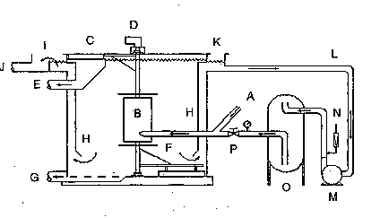
- Raw wastewater (A) mixes wiht the recycle water after the pressure release valve (P) and enters the DAF tank. The water is released into a coagulation tube (B) in the center of the tank. The water exits the top of the tube and the air bubbles carry the solids to the surface. Top skimmers (C) move the skimmings to the discharge trough (E) where they are collected. Treated water exits from the lower sections of the DAF through the riser tubes or shirt (H). Heavy solids that do not float settle to the bottom where a bottom skimmer (F) moves them to the discharge point (G) for removal.
- In the recycle loop, the clarified water is injected with air and pumped into a pressurization tank (O) where the air goes into solution. A pressure control valve (P) is used to maintain the desired pressure on the system. On the downstream side of the pressure control valve the pressure is released and the air comes out of the solution forrning microscopic bubbles.
Operating Principle
Air under pressure is dissolved into water according to Henry's Law of Dissolution. Releasing the pressure back to STP via a special device creates millions of micro bubbles approximately 30-100 microns in diameter. The micro bubbles attach to floc in the water and float it to the surface for removal.
The DAF unit includes the following sub-systems: flotation tank, contact chamber, skimming removal system, effluent discharge, re-circulation system air dissolving pipe. The specifications for each sub-system is described as follows:
A. Flotation Tank:
The unit consists of a flotation rank constructed of corrosion resistance coated carbon steel or 304 stainless steel plate and reinforced with corrosion resistance coated carbon steel or 304 stainless steel tubular vertical wall structural supports and horizontal cross member supports. The unit is supported on a stainless steel base consisting of horizontal beams across the width of the unit and a continuous beam structure down both sides of the length of the unit. The base is constructed to allow for easy cleaning around and under the unit.
B. Contact Chamber:
Influent wastewater enters the DAF unit through a flanged influent header into the contact chamber. The recycle stream is injected into the header nozzle prior to entry into the unit, and the recycle stream mixes with the influent. The contract chamber serves as an internal weir which provides even distribution and mixing of the process flow across the width of the unit. The contact chamber has a separate drain for removal of heavy solids which settle in the chamber.
C. Skimmings (Float) Removal System:
The unit is equipped with a chain and flight top skimmings removal system driven by a low speed, gear motor assembly. The top skimmer system shall consist of double strands of 304 stainless steel double pitch roller chain, guided by UHMW shoes on stainless steel angle. The chain supports adjustable, reinforced SBR skimmer blades retained on 304 stainless steel or fiberglass angle plates with stainless steel fasteners. The skimmer blades are spaced approximately every 5 ft. along the chainlength.
The chain system operates on single duty, carbon steel sprockets mounted on 303 stainless steel shafts turning in adjustable bearing supports. The system is driven by a variable speed drive (VFD) with TEFC motor through a chain and sprocket system. An adjustable torque limiter with automatic re-engagement shall be installed to protect the equipment in case of overload. Adjustable timer controls are installed to provide for intermittent skimmer operation which allows for flexibility in the removal of skimmings from the unit. Sprocket guards are provided for all four skimmer chain sprockets.
D. Effluent end, the bottoms trough is segregated from the effluent flow by a vertical baffle. A second vertical baffle directs the clarified effluent up into the header box and through and adjustable weir system. The weirs shall be adjustable and allow for up to 5" of vertical travel to determine the optimum liquid level in the unit, and they are designed to provide minimum fluctuation of the tank liquid level with the variation of influent flow. Clarified effluent overflowing the weirs collects in an internal trough and is discharged through a flanged nozzle.
E. Recirculation System:
Clarified wastewater from the discharge is recycled through the unit by a centrifugal pump designed to operate at pressures in excess of 85 psi. The pump features a cast iron casing, stainless steel shaft and bronze impeller, mechanical seals and a 460 V/3 ph/60 Hz/TEFC motor. Air is supplied into the recycle stream via an eductor loop from the discharge of the pump to the pump intake, drawing in ambient air and forcing it into solution with the recycle stream under pressure from the pump. Compressed air is added through this system via plant air. All recirculation piping is Sch80 PVC.
F. Air Dissolving Pipe (ADP):
A 304 stainless steel air dissolving pipe rated for 125 psi is equipped with an automatic pressure safety relief valve. Liquid level in the ADP is automatically maintained by an air release valve with an in-line equalizer. Discharge pressure from the recycle pump and the ADP is controlled by a diaphragm control valve with a EPDM diaphragm and a position indicator and a series of secondary whitewater injection points through stainless steel ball valves.
G. liquid filled pressure gauge was provided for monitoring recycle pressurization performance. The ADP was equipped with a 3/4" bottom drain valve and a 4" x 6" removable handway for inspection and servicing. The recirculation pump and ADP tank was mounted to the flotation tank.
 |
||
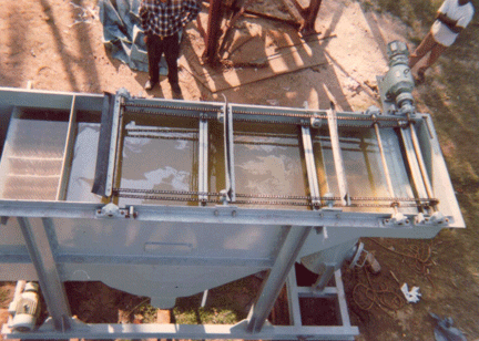
| Top View of D.A.F Unit | ||
 |
||
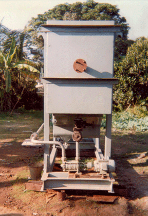
| Side View of D.A.F Unit | ||
 |
||
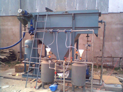
| Complete View of D.A.F Unit |
